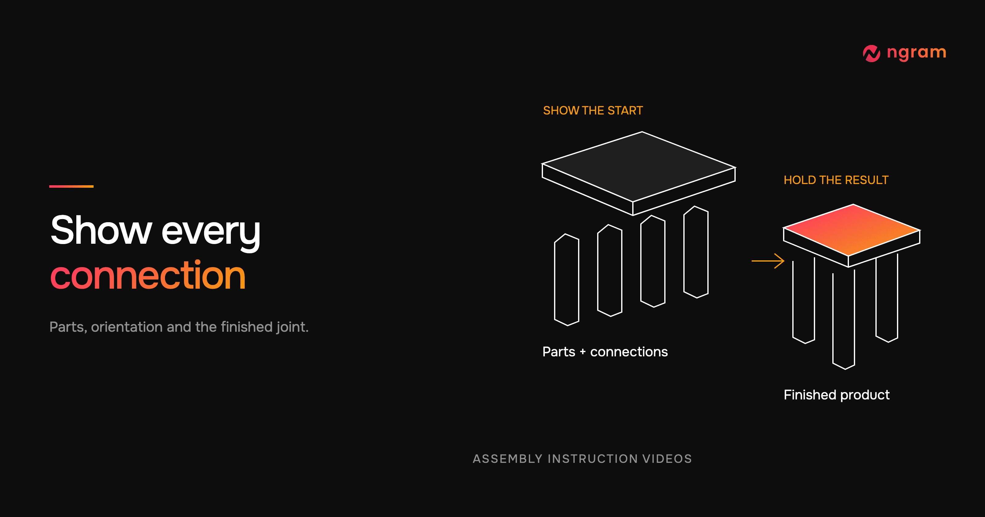

A customer can identify every part on a diagram and still hesitate at the joint. Assembly instruction videos earn their place when they make that missing movement visible: which end faces up, where the connector starts and what the completed connection looks like. For a product or support team, that is a more useful brief than “make this manual into a video.”
We used a short side-table assembly to work through those choices. The example is an independent illustration based on a particular manufacturer manual. The same planning questions apply when your product has a different connector, a different order or a longer setup.
1. Match the assembly instruction video to the current manual
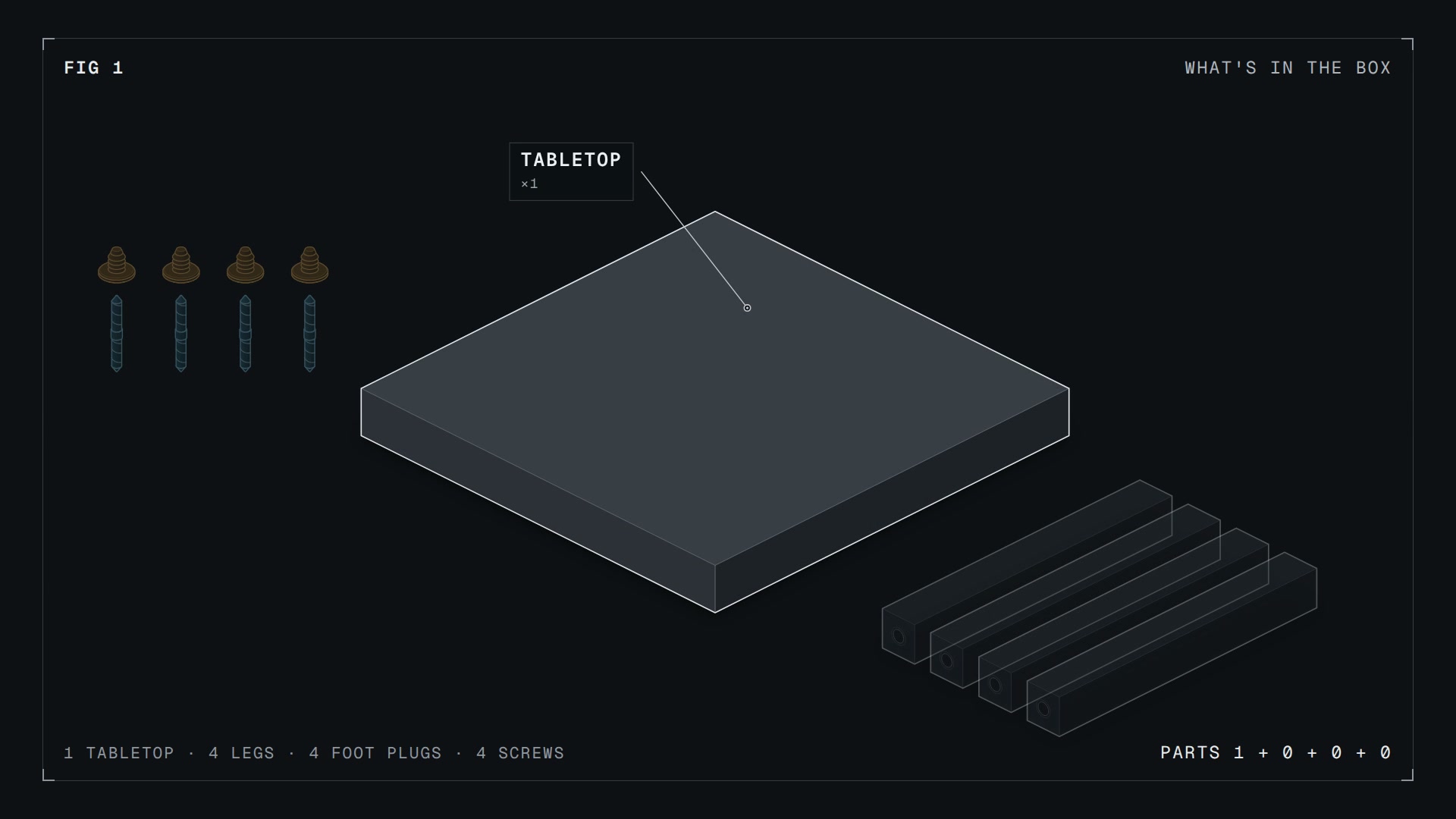
Start with the exact product variant and instructions the customer receives. For this example, we used IKEA LACK manual AA-2544912-1. It identifies a tabletop, four legs, four foot plugs and four double-ended screws. The foot plugs belong in this sequence; a video based on an older or different instruction sheet could miss them. Open the manufacturer’s assembly instructions.
Write the manual identifier into the production brief and keep the reference with the project. Ask the product owner to resolve any uncertain part or connection before the animator has to guess. When the product changes, compare the instructions first, then decide which shots need revision.
2. Show the starting orientation before the connection
The viewer needs a recognizable starting state. Name the components, show their quantity and orient the product before moving into a close view. For the side table, the tabletop turns face down onto a soft surface before its corner holes become the focus.
Use the same component appearance across the sequence. If the leg changes shape between the inventory and the joining shot, a beginner has to decide whether it is another part. Preserve a visible landmark, such as the open end of the leg or the corner of the tabletop, as the camera moves.
3. Make the joint the main action
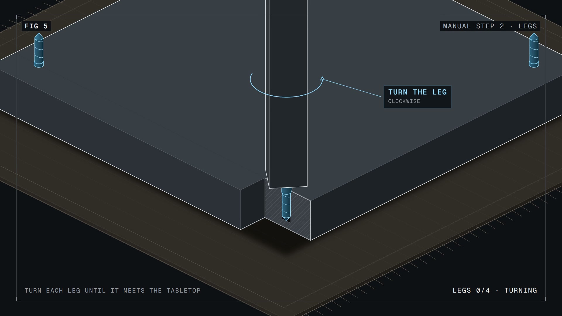
Give the important connection a beginning, movement and finished state. In the example, a foot plug starts outside the open leg end and presses in until it is flush. Later, the screw starts in a predrilled tabletop corner and the leg turns onto it. These are different actions and need different views.
A cutaway can explain the hidden screw connection while the wider assembly preserves orientation. Hold the joining point long enough to see the transition. For a recording, keep the hand and connector visible; for an illustration, check that the moving part reaches the correct endpoint without passing through the surrounding material.
4. Make repeated connections easy to count
After the first joint is understood, show how the remaining connections follow. Keep the completed pieces attached as the next one moves. A count can clarify progress, but it should agree with the picture: a “four complete” label cannot rescue a view with a missing leg.
Review one repeated component through the full sequence. Can the viewer trace it from the parts layout to its final position? A wider return view helps confirm that the close-up belongs to the same product and that the joining order still makes sense.
5. End on the finished product and its applicable limits
The final shot gives customers a state to compare with their own assembly. Show the completed product in its normal orientation, with enough time to recognize the relevant connections. Carry forward the limits that apply to that item. In the LACK reference, those include a maximum load of 10 kg and an instruction not to sit on the table.
Keep the source credit readable and independent of the product’s branding. The example credits the manual without using the manufacturer’s logo or implying endorsement. For your own product, place the reviewed video beside the applicable instructions so the reference remains easy to find.
A real assembly animation from the same brief
The resulting video runs 44.8 seconds and moves through six figures: parts, preparation, foot plugs, screws, legs and the finished table. That length describes this result, not a recommended limit for every assembly. A more complex joint may need a longer hold or a separate clip.
From this input to this video
An independently illustrated assembly follows IKEA LACK manual AA-2544912-1: parts, foot plugs, screws, attached legs and the finished upright table.
Prompt
Create a 40-second 16:9 assembly explainer for someone putting together an IKEA LACK side table for the first time. Use this manufacturer's manual as the factual source: https://www.ikea.com/es/en/assembly_instructions/lack-side-table-white__AA-2544912-1-2.pdf (manual AA-2544912-1). Show an independently drawn isometric technical illustration in Machine anatomy style, with clear labels and close views of the connections. No presenter. Use friendly English narration, readable labels and no background music. Show the sequence from this exact manual: identify the tabletop, four legs, four foot plugs 153551 and four double-ended screws 115980; protect the tabletop on a soft surface while it is upside down; insert one foot plug into the open end of each leg, pressing it flush by hand as in manual step 1; start each double-ended screw into a predrilled tabletop corner by hand; then turn each leg onto its screw until it meets the tabletop, as in manual step 2; show the same four legs becoming attached, then turn the completed table upright. Preserve the tabletop and all four legs throughout the sequence. Show a close view of one joint so the viewer understands how the screw connects the tabletop and leg, then repeat for the other corners. Keep screw direction and part counts consistent. Do not invent tools, torque values, drilling or product dimensions. Close with the manual's limits in plain English: do not sit on the table; maximum load 10 kg. Add a concise source credit: Independent illustration based on IKEA LACK manual AA-2544912-1. No IKEA logo and no suggestion of endorsement. End on the complete upright table. Let the viewer see each connection long enough to follow it.
Selected style
Machine anatomy
Read the video transcript
Let's build a LACK side table. In the box: one tabletop, four legs, four foot plugs and four double-ended screws. Lay the tabletop upside down on something soft, like a rug, to protect it. Press a foot plug into the open end of each leg by hand until it sits flush. Now start a double-ended screw into each predrilled corner, turning it by hand. Turn a leg onto its screw until it meets the tabletop. The screw joins the two. Repeat for the other three corners. Flip the table upright and it's ready. Please don't sit on it, and keep the load to 10 kg or less.
A side-table assembly, from parts to finished product
Watch the actual illustrated result and read the manual-based brief. Adapt the starter for your product and its current instructions.
Bring the current instructions
Replace the product, manual version, parts and joining order in the brief.
Plan the connections
Use Machine anatomy with Opus 5.5. Review the parts, narration and sequence before approving the plan.
Inspect the finished assembly
Compare the connections and final state with the source, then request specific corrections before sharing.
Make it yours
Fill in your details here, or continue and finish your brief in ngram.
Video generation uses credits. Review your estimate in ngram. MP4 downloads require Basic or higher.
How credits workMethod: we supplied the public manual, product identifier, part count, joining sequence and limits in one initial brief, then approved the proposed plan in Studio. The saved output is a drawn explanation of that reference. It does not use an imported CAD model or filmed assembly footage.
Choose a recording, an illustration or a model-based view
| Viewer needs to inspect | Useful starting point |
|---|---|
| A hand position, tool or real surface | A recording of the approved procedure |
| A hidden connection or simplified relationship | A reviewed technical illustration |
| The actual engineering assembly geometry | An animation of the existing model |
Use an illustration when the hidden relationship is what needs explaining. If the deliverable depends on retaining the product’s engineering geometry, use a model-based workflow. Read the technical animation and CAD workflow comparison.
For the illustrated path in ngram, describe the audience, parts and sequence, then choose Machine anatomy with Opus 5.5. Voice Auto and Presenter No avatar are recommended for narration over the figure. The technical-animation guide shows the Studio setup.
Questions about assembly instruction videos
How long should an assembly video be?
Give each meaningful connection enough time to understand. Show one repeated joint in detail, then make the remaining repetitions clear. Split a long assembly into stages when customers need to find a particular step.
Can I make animated assembly instructions from a manual?
Yes, when the brief identifies the product version, parts and sequence to preserve. Have the product owner review the resulting motion against those instructions. A finished render still needs that factual review.
Where should a product assembly video live?
Put it where customers look for setup: beside the current manual, on the relevant product support page or in post-purchase guidance. Plan the product assembly workflow.